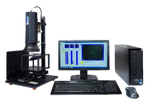
Being in the niche engineering field of optics, metrology is essential for optical coatings QA (quality assurance) and creating products produced to specification. Simply put, if you can’t measure it, you cannot manage it. That is why we are very pleased to announce the new addition to our metrology department: the SavvyInspector.
The SavvyInspector is designed to take the subjective element out of scratch and dig QA. By allowing for objective measurement of scratch / dig visibility, the human element has been removed thereby ensuring consistency of production quality.
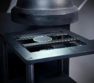
AÂ standard inspection begins with a visual scan of the optic surface using
a high-intensity fiber lamp to create an initial map of imperfections that will be evaluated. While mapping the optic surface, the inspector may record scratch lengths to be used for accumulation. The optic is then loaded into the SavvyInspector and calibration is selected for evaluating each defect. Images of each defect may then be stored for later reference.
Values of the surface imperfections are then entered into surface quality inspection software and a report is generated detailing whether the optic has passed or failed the surface quality inspection.
Best used on the following optical coatings:
Calibrated to the most common and respected Davidson Optronics, Brysen Optical, and Jenoptik standards, the SavvyInspector ensures flexibility and consistency to industry standards while also allowing for customized calibration settings.

Below are the scratch / dig calibrations that are supported:
Inspection Head
0.5 Megapixel camera and fixed illumination and simulating reflection inspection for surface quality per MIL-PRF-13830B
Inspection setup is identical to that of MIL-PRF-13830B Annex C, MIL-C-675C and the visibility method described in ANSI/OEOSC OP1.002:2009
Camera Field of View
9 x 12 mm, digitally zoomable
Allows rapid location of imperfections
Inspection Area
One mm square in center FOV Allows isolation of specific imperfection for evaluation X-Y Stages Manual encoded x, y slide stage with >100mm travel
Encoders read out distance moved since last mouse click allowing rapid evaluation of scratch length
Focus Manual
70 mm Z-stage for focus. Depth of focus > 1 mm
Easily accommodates thick parts
Test Surface Reflectivity
System can measure coated or uncoated parts, filters, windows, splitters, cubes, and prisms.
Standard calibration files for metalized comparison standards are provided. Some custom calibrations or part fixturing may be required.
Test Surface Shape
Plano or mild concave surface
Designed for flat parts, but long radius concave parts can also be inspected
Reported Values
Scratch number- 10, 20, 40, 60, 80
Dig value – continuous from 5 to 70
ISO Grade – 0.063 to 0.63
Per MIL-PRF-13830B and ANSI/OEOSC OP1.002, visibility method ISO 10110-7 general and coating imperfections only
Comparison Standards
Factory calibrated to FLIR/Brysen, Davidson comparison artifacts, as well as various plastic inspection paddles
Customer can generate and save calibration files for any artifact set